obdlaunch
Engine Crankshaft Flywheel Tensioner Locking Alignment Timing Tool Set AUDI A4 A6 3.0 V6 AVK Engine Series
Engine Crankshaft Flywheel Tensioner Locking Alignment Timing Tool Set AUDI A4 A6 3.0 V6 AVK Engine Series
Regular price
$84.00
Regular price
$0.00
Sale price
$84.00
Unit price
per
Shipping calculated at checkout.
Couldn't load pickup availability
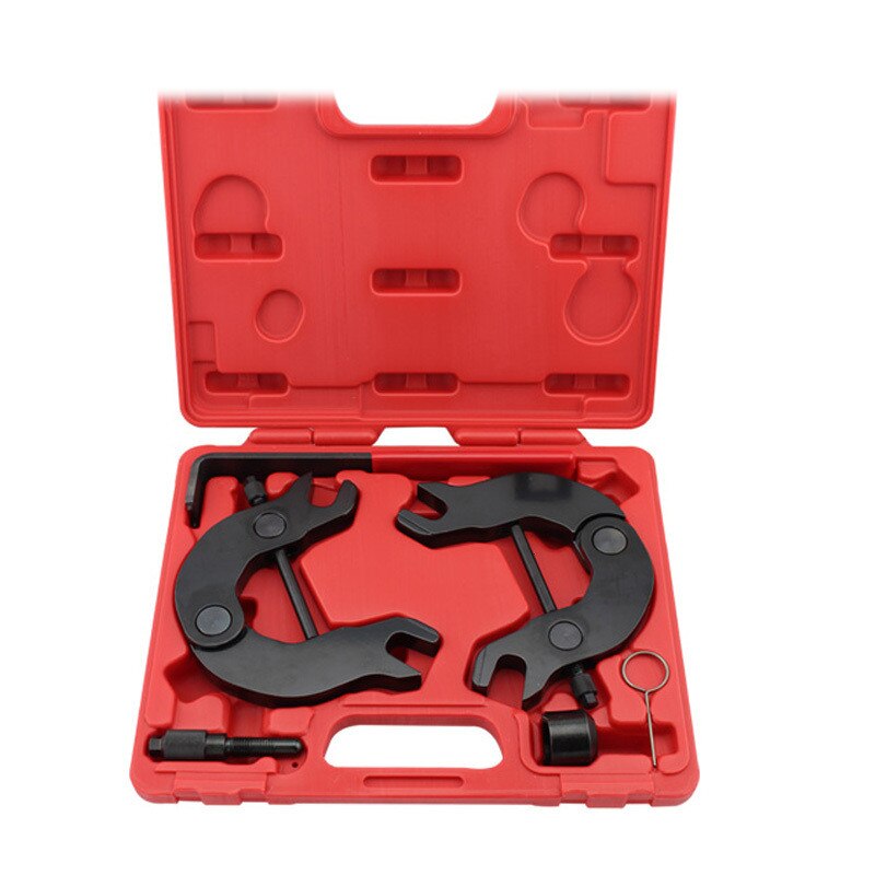
Engine Crankshaft Flywheel Tensioner Locking Alignment Timing Tool Set For AUDI A4 A6 3.0 V6 AVK Engine Series ST0140
Product Contains:
2 Camshaft Locking C fixtures (for left and right cams)
TDC Locating Locking Pin
3/8" Drive Camshaft Adjuster Socket (Turns the exhaust cams timing back)
Tensioner Locking Pin
Tensioner Wrench with grip
Please note that this tool is only applicable to the 3.0L V6 AVK series of engines that are installed in Audi A4 and A6 platforms from 2000-2004. It is not applicable to any 5-valve engines.
The two locking / adjustment fixtures interface with the camshafts and are for the critical task of securing and maintaining TDC timing alignment when the cam belt is serviced or removed for other front-engine or cylinder head service tasks.
Long pin for locating the crankshaft at TDC (Top Dead Center) when timing the engine or servicing the timing belt or flywheel / drive plate.
Special 3/8" drive socket designed specifically to adjust the variable valve timing on the exhaust camshaft to the base position when performing timing belt or other front-engine service on Audi 3.0L, 5 valve engines.
Application:
Audi 3.0L V6 AVK series of engines that are installed in Audi A4 and A6 platforms from 2000-2004
Recommended Instructions of use:
Step 1: Securely support the vehicle with jack stands or frame lift, then remove the rear wheels per factory manual.
Step 2: Remove both front mounting bolts from the rear axle mounting bracket.
Step 3: Pull the front end of the trailing arm down the mounting bracket and wedge into position, using a solid object between the arm end and the underside of the vehicle.
Step 4: Mark the exact position in the arm of the rubber mounting.
Step 5: Remove the old mounting bush from the trailing arm.
Step 6: Lubricate the screw threads of the tool.
Step 7: Align the Y mark on the new bush with the mark on the axle trailing arm.
Step 8: Assemble the bush suspension tool and insert the new bonded mounting into position (see picture above) adapter is lipped and designed to sit flush against the trailing arm.
Step 9: With a 24mm socket on ratchet slowly turn the thrust bearing to pull the new mounting into the rear axle.
Step 10. Re-assemble and Repeat steps 3-9 for the other side.